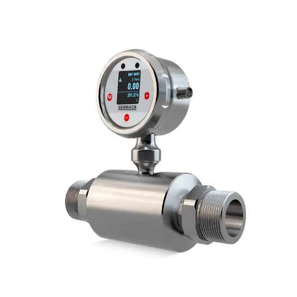
FlowM260 Electromagnetic Flowmeter
Main Features
- Four Process Connection Version
- Local Display
- Large Working Temperature for liquid media
- Stainless Steel body and sensor electrode
- 4-20 mA, Pulse and Rs485 Modbus
- Robust Design
| G1/4" | G1/2" | G1" | G1-1/2" | |
|---|---|---|---|---|
| DN format | DN4 | DN8 | DN15 | DN25 |
| Measuring Range | 0,1...10 l/m | 0,5...25 l/m | 2...100 l/m | 4...200 l/m |
| Accuracy | <0,5 % of Full Range | |||
| Repeatability | <0,2 % of Full Range | |||
| Working Temperature | -25...+120 ºC (no thermal shock) | |||
| Ambient Temperature | -25...+80 ºC | |||
| Working Pressure | max 16 Bar | |||
| Response Time | 100 ms | |||
| Medium | Conductive Liquid (Conductivity should be higher than 20 uS/cm) | |||
| Materials |
Electrode and Process Connection : 316T Measuring Tube : Peek Housing : 304 Seal : EPDM |
|||
| Power Supply | 24 Vdc (+-%10). consumption is <100 mA | |||
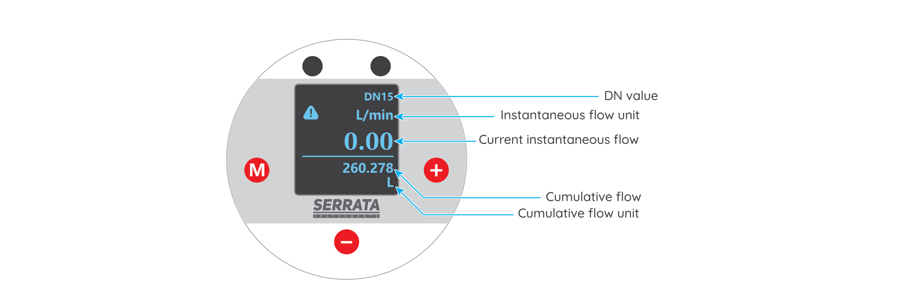
| Display | 4 Row LCD; instantaneous flow, unit cumulative flow and its unit. | |||
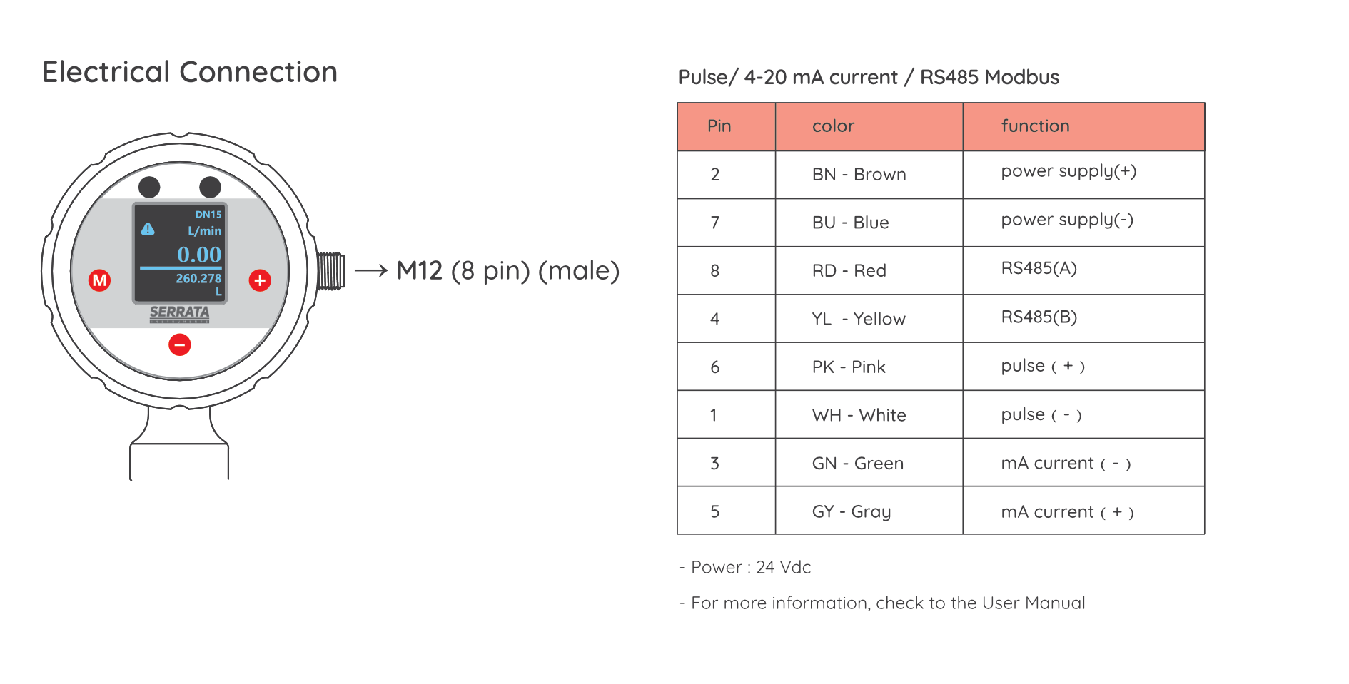
| Outputs | 4-20 mA, Pulse and Rs485 Modbus (M12 8 pins connector) | |||
| Setup | only 3 button on device | |||
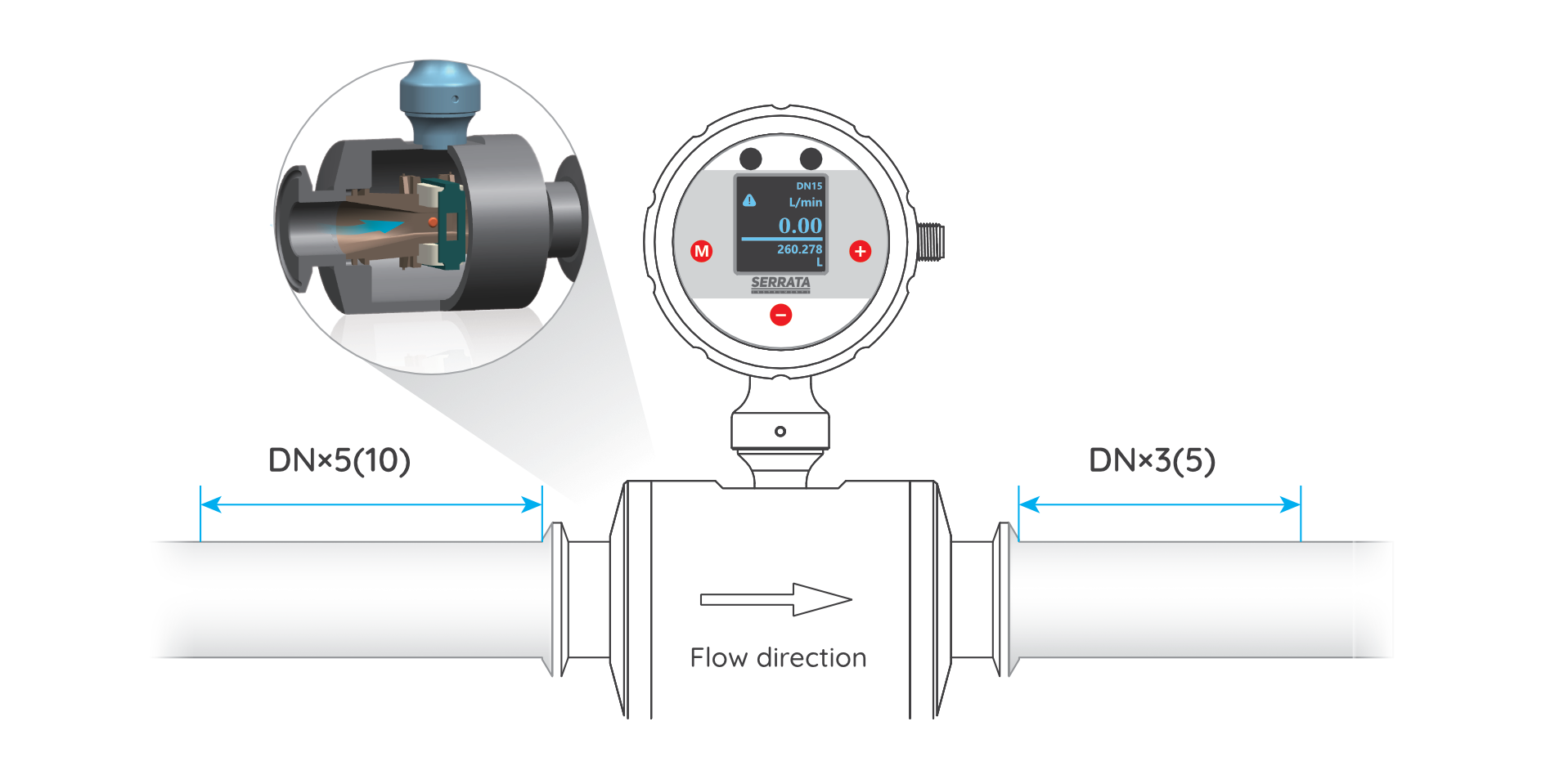
Flowmeter Installation Method
Select an installation position
The straight pipe section where the fluid flow isstable in the piping system should be selected. Generally, the length of the upstream straight pipe section is 5 to 10 times the pipe diameter, and the length of the downstream straight pipe section is 3 to 5 times the pipe diameter. Stay away from strong magnetic fields and strong electric field interference sources, suchas large motors, transformers, high-voltage lines, etc. If it is not possible to stay away, shielding measures should be taken. The installation position should be easy to maintain and repair, and have enough operation space.
Flowmeter Installation Method
Horizontal installation:
The electromagnetic flowmeter can be installed horizontally, but it is necessary to ensure that the electrode axis is parallel to the ground, and the pipes at both ends of the flowmeter should be on the same horizontal plane to avoid high and low drop.
Vertical installation:
can also be installed vertically, this time should ensure that the electrode axisand the ground vertical.
Installation Precautions
Handle the flowmeter gently during installation to avoid collisionand falling.
Install in strict accordance with the product instructions, and do not arbitrarily change the installation method and connection line. After the installation is complete, check whether the connection parts are secure and the cables are correctly connected.


Content is preparing
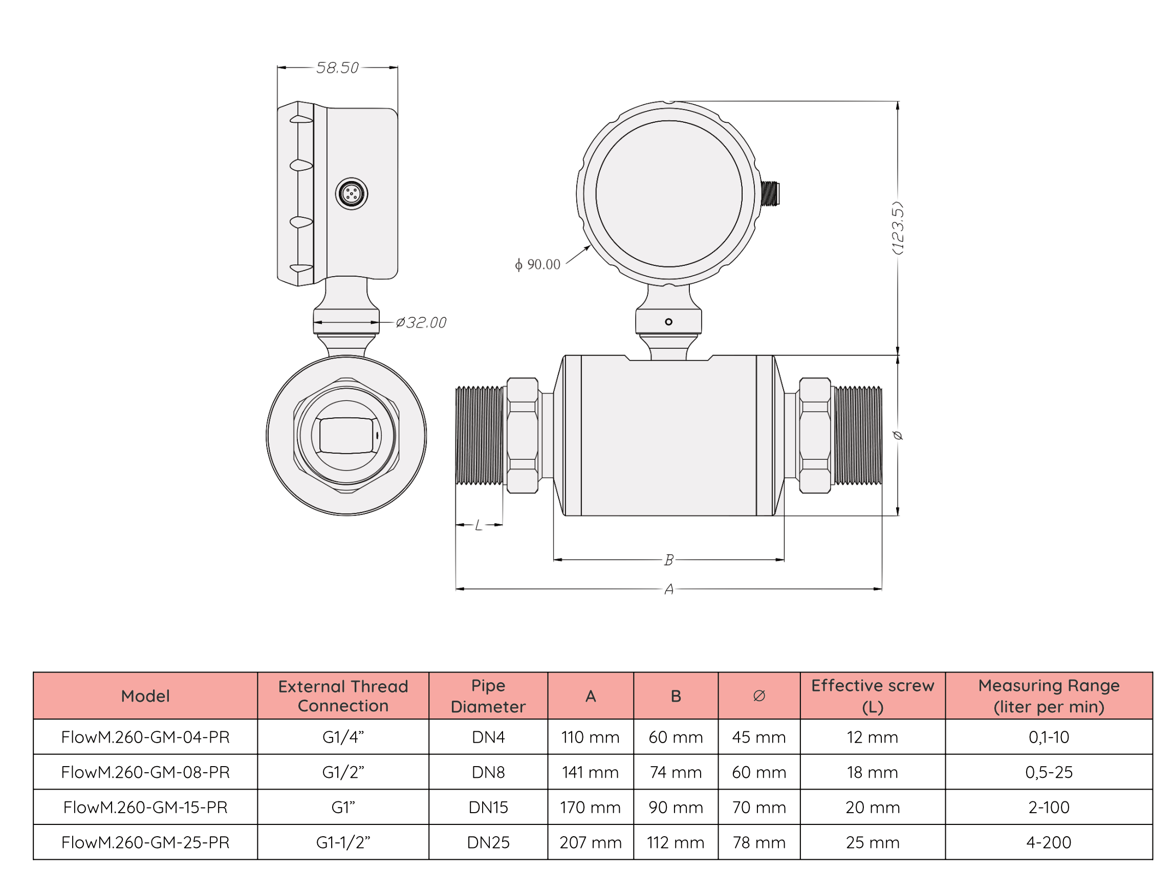
| Order Code | Process Connection | DN Norm | Range |
|---|---|---|---|
| FlowM.260-GM-04-PR | G1/4" | DN4 | 0,1...10 l/min |
| FlowM.260-GM-08-PR | G1/2" | DN8 | 0,5...25 l/min |
| FlowM.260-GM-15-PR | G1" | DN15 | 2...100 l/min |
| FlowM.260-GM-25-PR | G1-1/2" | DN25 | 4...200 l/min |